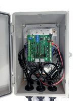
Description
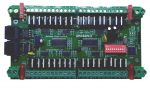
DMX2-24
24 Channel DC dmx controlled dimmer for 2 wire, 2 channel LED strings
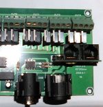
2 x RJ45 DMX connectors wired to ESTA standard configuration
20-40V power input
2A maximum per output
Switchable test mode
Switchable mode to allow both channels of the 1 string to function as 1 dmx channel (12 channel mode)
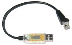
A power supply , a USB-DMX dongle (or E1.31 to DMX bridge) and a computer (or Raspberry Pi or BeagleBone Black running FPP) is what is needed to control Christmas lights.
Typically the style lights that this controller is used for uses a 31V power supply. There is 1 here. A 31V 200W power supply will generally run around 30 strings of 2 wire 2 channel lights but this will depend entirely on the light set. Strings of 100 will be different to strings of 1000.
Preliminary/draft user manual is available here. Video showing the operation to follow soon.
For testing I recommend using da_tester from http://www.da-share.com/software/
For more information on connecting and running Christmas lights visit http://auschristmaslighting.com and for the 1 step guide have a look at http://auschristmaslighting.com/wiki/AusChristmasLighting_101 or browse http://auschristmaslighting.com/wiki/Main_Page
David Duffy of Audio Visual Devices has a page (http://www.da-share.com/circuits/2-wire-led-strings/) that has some information on the 2 wire, 2 channel led strings that this controller is used on. Lytworks lights from Bunnings as well as ones from Big W and other retail stores are mostly going this way.
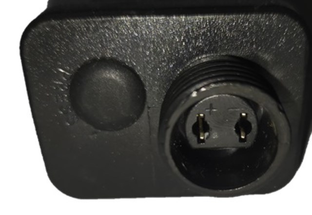
2 wire, 2 channel led strings can be identified by the fact that there is a multifunction controller either as part of the power supply or inline with the wires from the power supply and from there out to the leds there are only 2 wires.
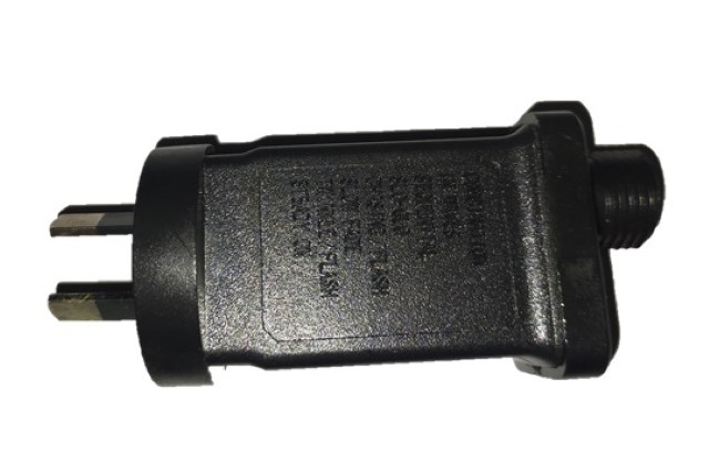
The controllers that this board is designed to replace have a typical appearance like below.

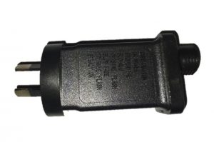
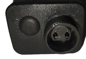
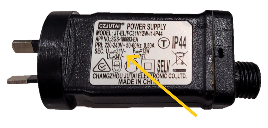
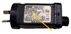
This style controller comes in numerous different voltages from 5V up to 36V. All 12 strings that get connected to the DMX2-24 should be the same voltage (within a few volts). The voltage of the lights/controller can be seen as in the picture below. Lights in the range from about 27V-36V can generally all be ran from a 31V power supply. If all the lights are the same voltage the S200-31 and S400-31 (and the other voltage supplies) are adjustable +/-10%.
The DMX2-24 is unsuitable for voltages below 12V.
The DMX2-24 is NOT SUITABLE to control the 2 wire Twinkly lights. The Twinkly lights are a brand name and they are a 2 wire pixel. Each led on a Twinkly string of lights can be any colour. The usual control of Twinkly lights is either via an app or a remote control that has a full colour pallette on it.
Firmware updates
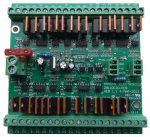
Firmware updates can be loaded through the ICSP header with a Pickit3 pic programmer. Pin 1 of the ICSP header is marked on the pcb and is shown to the left. Ensure the pin 1 (the arrow) of the header is aligned with pin 1 of the programmer.
Via MPLAB
MPLAB must be installed. It is available from microchip.com
Plug your PicKit 3 into a spare USB port, then start MPLAB X IDE (or version 8.84 or whatever). Once it has loaded, click Configure > Select Device to bring up the device selection window. From the device drop-down list, select PIC16F884 and click OK.
A dialog saying \”New firmware must be downloaded for PicKit 3 to work with the part selected.\” may pop up at this stage. If it does, click OK and wait for MPLAB to download the programming firmware to the Pickit 3. You will see some activity in the PicKit 3 tab of the output window for up to a minute or so. When MPLAB is ready you will see \”PicKit 3 Connected\” and possibly an error stating \”PK3Err0045: You must connect to a target device to use Pickit 3\”. This is not a problem and just a warning that the PicKit 3 cannot \”see\” the chip yet.
Then, click File > Import and browse to the DMX2-24 1.0 HEXFILE.hex file (latest version at time of writing) and click Open. The last line of the build tab of the output window should read \”Loaded C:…DMX2-24****.HEX.\”
Now, connect the PicKit 3 the 6 pin ICSP header next to the micro. Make sure the arrows on the Pickit 3 and the 6 pin header are aligned. Then power up the DMX2-24. The PicKit 3 tab of the output window should now read \”Target Detected”.
Click Programmer > Program to initiate the ICSP operation. The PicKit 3 tab of the output window will show \”Programming…\”, then \”Programming/Verify complete\” once it is done. Disconnect the PicKit 3. The PicKit 3 tab of the output window will show \”Target Removed\”.
Via “Programmer To Go” feature of PicKit3
If a PicKit 3 has been preprogrammed with firmware then all is required is that the DMX2-24 board is powered up. Plug the PicKit3 onto the header as shown above. Power the PicKit3 by plugging it into any usb socket. The power led on PicKit will light, the status led will be green and the blue active led will be flashing. Press the pushbutton. The status led will turn red, the active led will turn solid red. When then Status led turns green again and the blue Active led starts flashing the firmware has been updated.
Via “PicKit 3Programmer” software
The Pickit 3 programmer software can be downloaded at http://ww1.microchip.com/downloads/en/DeviceDoc/PICkit%203%200.3.3.0%20Setup%20A.zip .
Extract and run in. Select PIC16F884 as the Device. Select File>Import Hex> and browse to the DMX2-24 1.2 HEXFILE.hex file (latest version at time of writing) . Plug in the PicKit 3. If the DMX2-24 is powered then click on write and it will update the firmware. If the board isn’t powered then click on the “On” button in the “Target Power” section. The power and mode light on DMX2-24 should then power up. Click on “Write”.
Latest hex file is at https://www.hansonelectronics.com.au/wp-content/uploads/2023/10/DMX2-24-ver-1.1.zip
The processor is a PIC16F884 with PIC16F886 also used on some boards. With some PIC16F884 processors it is necessary to turn on the “classic” switch while programming.